|
|
 |

Before strain gage-based load cells became the method of choice for industrial weighing applications, mechanical lever scales were widely used. Mechanical scales can weigh everything from pills to railroad cars and can do so accurately and reliably if they are properly calibrated and maintained. The method of operation can involve either the use of a weight balancing mechanism or the detection of the force developed by mechanical levers. The earliest, pre-strain gage force sensors included hydraulic and pneumatic designs.
In 1843, English physicist Sir Charles Wheatstone devised a bridge circuit that could measure electrical resistances. As was discussed in detail in Chapter 2, the Wheatstone bridge circuit is ideal for measuring the resistance changes that occur in strain gages. Although the first bonded resistance wire strain gage was developed in the 1940s, it was not until modern electronics caught up that the new technology became technically and economically feasible. Since that time, however, strain gages have proliferated both as mechanical scale components and in stand-alone load cells.
Today, except for certain laboratories where precision mechanical balances are still used, strain gage load cells dominate the weighing industry. Pneumatic load cells are sometimes used where intrinsic safety and hygiene are desired, and hydraulic load cells are considered in remote locations, as they do not require a power supply. Strain gage load cells offer accuracies from within 0.03% to 0.25% full scale and are suitable for almost all industrial applications.
In applications not requiring great accuracy--such as in bulk material handling and truck weighing--mechanical platform scales are still widely used. However, even in these applications, the forces transmitted by mechanical levers often are detected by load cells because of their inherent compatibility with digital, computer-based instrumentation. The features and capabilities of the various load cell designs are summarized in Figure 7-1.
| Figure 7-1: Load Cell Performance Comparison |
| TYPE OF LOAD CELL |
WEIGHT RANGE |
ACCURACY (FS) |
APPLICATIONS |
ADVANTAGES |
DISADVANTAGES |
| Mechanical Cells |
| Hydraulic |
Up to 10,000,000 lb |
0.25% |
Tanks, bins and hoppers.
Hazardous areas. |
Takes high impacts,
insensitive to temperature. |
Expensive, complex. |
| Pneumatic |
Wide |
High |
Food industry, hazardous areas |
Intrinsically safe.
Contains no fluids. |
Slow response.
Requires clean, dry air |
| Strain Gage Cells |
| Bending Beam |
10-5,000 lb |
0.03% |
Tanks, platform scales, |
Low cost, simple construction |
Strain gages are exposed,
require protection |
| Shear Beam |
10-5,000 lb |
0.03% |
Tanks, platform scales,
off- center loads |
High side load rejection, better
sealing and protection |
|
| Canister |
to 500,000 lb |
0.05% |
Truck, tank, track, and hopper scales |
Handles load movements |
No horizontal load protection |
| Ring and Pancake |
5- 500,000 lb |
|
Tanks, bins, scales |
All stainless steel |
No load movement allowed |
| Button and washer |
0-50,000 lb
0-200 lb typ. |
1% |
Small scales |
Small, inexpensive |
Loads must be centered, no
load movement permitted |
| Other Types |
| Helical |
0-40,000 lb |
0.2% |
Platform, forklift, wheel load,
automotive seat weight |
Handles off-axis loads,
overloads, shocks |
|
| Fiber optic |
|
0.1% |
Electrical transmission
cables, stud or bolt mounts |
Immune to RFI/EMI and
high temps, intrinsically safe |
|
| Piezoresistive |
|
0.03% |
|
Extremely sensitive, high
signal output level |
High cost, nonlinear output |
Operating Principles
Load cell designs can be distinguished according to the type of output signal generated (pneumatic, hydraulic, electric) or according to the way they detect weight (bending, shear, compression, tension, etc.)
Hydraulic load cells are force -balance devices, measuring weight as a change in pressure of the internal filling fluid. In a rolling diaphragm type hydraulic load cell, a load or force acting on a loading head is transferred to a piston that in turn compresses a filling fluid confined within an elastomeric diaphragm chamber. As force increases, the pressure of the hydraulic fluid rises. This pressure can be locally indicated or transmitted for remote indication or control. Output is linear and relatively unaffected by the amount of the filling fluid or by its temperature. If the load cells have been properly installed and calibrated, accuracy can be within 0.25% full scale or better, acceptable for most process weighing applications. Because this sensor has no electric components, it is ideal for use in hazardous areas.
One drawback is that the elastomeric diaphragm limits the maximum force that can be exerted on the piston to about 1,000 psig. All-metal load cells also are available and can accommodate much higher pressures. Special metal diaphragm load cells have been constructed to detect weights up to 10,000,000 pounds.
Typical hydraulic load cell applications include tank, bin, and hopper weighing. For maximum accuracy, the weight of the tank should be obtained by locating one load cell at each point of support and summing their outputs. As three points define a plane, the ideal number of support points is three. The outputs of the cells can be sent to a hydraulic totalizer that sums the load cell signals and generates an output representing their sum. Electronic totalizers can also be used.
Pneumatic load cells also operate on the force-balance principle. These devices use multiple dampener chambers to provide higher accuracy than can a hydraulic device. In some designs, the first dampener chamber is used as a tare weight chamber. Pneumatic load cells are often used to measure relatively small weights in industries where cleanliness and safety are of prime concern.
The advantages of this type of load cell include their being inherently explosion proof and insensitive to temperature variations. Additionally, they contain no fluids that might contaminate the process if the diaphragm ruptures. Disadvantages include relatively slow speed of response and the need for clean, dry, regulated air or nitrogen.
 |
| Figure 7-2: Wheatstone Circuit with Compensation
|
Strain-gage load cells convert the load acting on them into electrical signals. The gauges themselves are bonded onto a beam or structural member that deforms when weight is applied. In most cases, four strain gages are used to obtain maximum sensitivity and temperature compensation. Two of the gauges are usually in tension, and two in compression, and are wired with compensation adjustments as shown in Figure 7-2. When weight is applied, the strain changes the electrical resistance of the gauges in proportion to the load.
Other load cells are fading into obscurity, as strain gage load cells continue to increase their accuracy and lower their unit costs. Some designs, however do continue to enjoy limited use:
Piezoresistive: Similar in operation to strain gages, piezoresistive sensors generate a high level output signal, making them ideal for simple weighing systems because they can be connected directly to a readout meter. The availability of low cost linear amplifiers has diminished this advantage, however. An added drawback of piezoresistive devices is their nonlinear output.
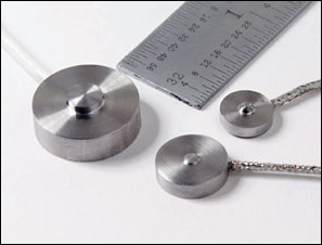 |
| Button style compression load cells.
|
Inductive and reluctance: Both of these devices respond to the weight-proportional displacement of a ferromagnetic core. One changes the inductance of a solenoid coil due to the movement of its iron core; the other changes the reluctance of a very small air gap.
Magnetostrictive: The operation of this sensor is based on the change in permeability of ferromagnetic materials under applied stress. It is built from a stack of laminations forming a load-bearing column around a set of primary and secondary transformer windings. When a load is applied, the stresses cause distortions in the flux pattern, generating an output signal proportional to the applied load. This is a rugged sensor and continues to be used for force and weight measurement in rolling mills and strip mills.
|